In order to provide high quality experimental data for model validation, TU Berlin operates different combustion test rigs within the ESTiMatE project. One of those is a turbulent counter flow setup, where two streams, one carrying fuel and one carrying the oxidizer, eject from two opposing nozzles. The resulting flow field leads to a flame that is distributed mostly flat. The test rig was designed and manufactured last year. Over the last couple of months, the commissioning phase of the setup could be carried out and first fire was achieved.

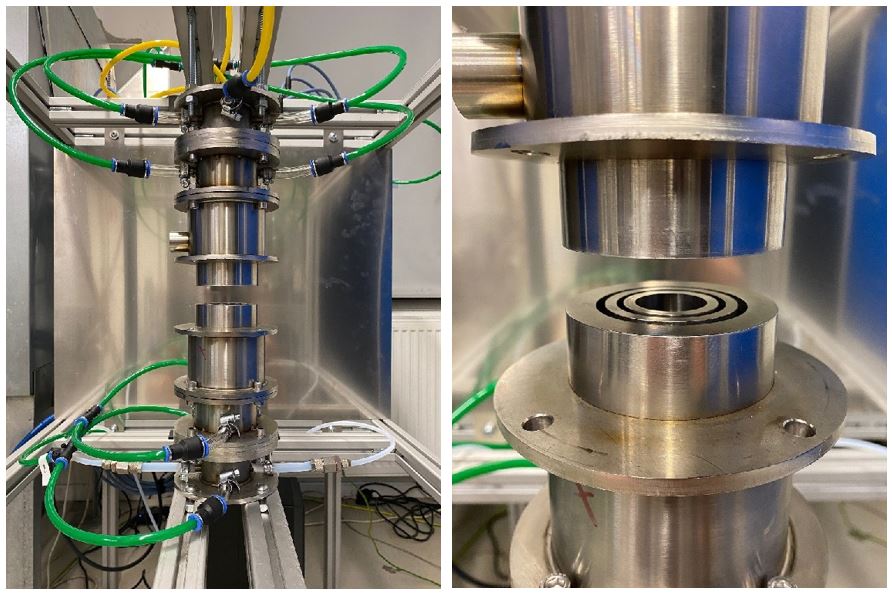
Figure 1 depicts the burner, which consists of two opposing elements. Ethylene fuel is mixed with nitrogen and ejected from the central nozzle of one element, while the other element ejects an oxygen/nitrogen mixture. The mixture ratios are chosen such that the two streams have similar velocity. The two reactant plena are further equipped with turbulence generators to achieve a specific amount of turbulence intensity. A heat release of up to 10 kW is possible with this setup. Both reactant streams are also shielded by secondary nitrogen streams emanating from the middle annulus as shown in Fig. 1. This further contains the heat release zone and increases flame compactness. Finally ,an outlet port is available in the upper element. This port, which is connected to a venture nozzle fed with air, allows venting of combustion gases away from the reaction zone.
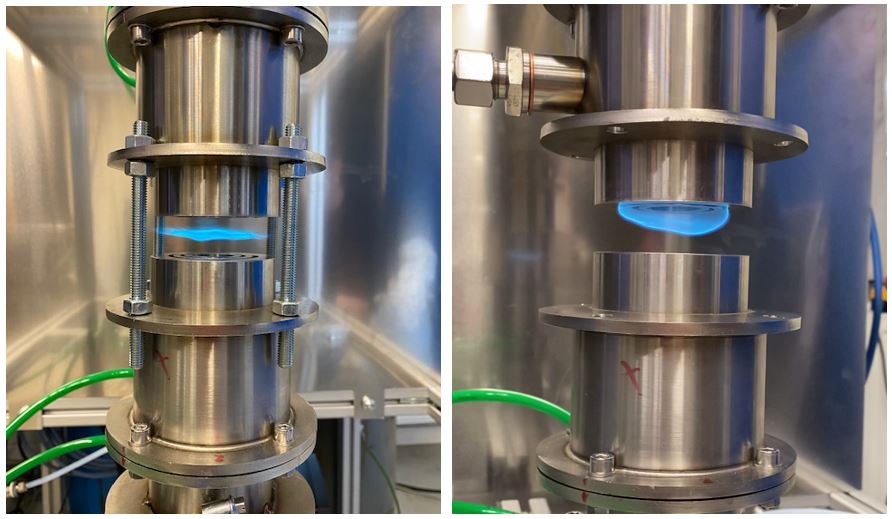
Successful operation of the counter flow flame was achieved, as shown in Figure 2. A centering concept was developed to precisely adjust radial and axial alignment of the two nozzles, such that the threaded rods (still shown in Fig. 2 (left)) are no longer necessary. The heat release zone takes on the expected shape and it was possible to adjust the thermal power as required, rendering the commissioning period a success.
In the next phase, an operating point with adequate soot loading will be determined, which requires a delicate balance of air fuel ratio, reactant stream momentum, and temperature in the reaction zone. Then, advanced diagnostics will be applied: particle image velocimetry (PIV) to determine the flow field characteristics, and laser-induced incandescence to spatially quantify soot volume fraction and particle size distribution, supporting model validation.