
The ESTiMatE project aims to provide a comprehensive data set for the validation of numerical models, which will be developed in terms of the project. To fulfill this aim, a swirl-stabilized combustor with a liquid fuel injection nozzle will be investigated by Technische Universität Berlin (TUB). The combustor will be capable of operating over a broad range of equivalence ratios including under-stoichiometric and over-stoichiometric operation in the primary reaction zone. In the subsequent parts of the combustion chamber quenching air injections will be applied in order to force burn out of hydrocarbons according to the Rich-Burn, Quick-Mix, Lean-Burn (RQL) combustor concept, which aims to reduce oxides of nitrogen (NOx) emission from gas turbine engines. Various operational parameters such as equivalence ratios in the different reaction zones, defined by the quenching and leaning mass flows will be employed.
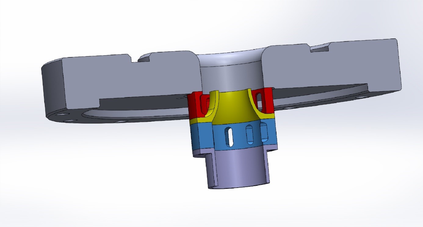
The investigated atomiser which was designed and delivered at TUB, is an assembly based on the Airblast concept (Fig. 1.) [1]. It consists of a modular arrangement of two radial swirl generators, an atomizer lip which separates the two airstreams from each other within the nozzle, and an air diffuser. Liquid fuel is delivered to the atomizer through an atomizer along the axis of the nozzle holder. The primary airflow is fed at the lower half of the nozzle holder and is then surrounded by secondary air, which is supplied through a connecting section at the upper half of the nozzle assembly. In case of the attached-stabilized flame, the swirl number of the primary swirl body results in the breakdown of the vortex, whereas the construction of the secondary radial swirler ensures that the flame remains attached to the nozzle duct. The theoretical swirl numbers of the primary as well as of the secondary swirler resulted according to Leuckel [2], based on the geometry data of the swirl generators, as the ratio of the angular to the axial flux momentum divided by the narrowest radius of each inner and outer channel. Particularly for the assembly used in terms of the ESTiMatE project the total swirl number is 0.78.
At this stage an experimental campaign for the definition of the flow field resulting from the application of the described nozzle was conducted at TUB. The experimental setup used was the water test rig of TUB [3]. The test facility was subjected to the implementation of non-intrusive experimental fluid mechanics techniques; therefore, it is fully optical accessible through four glass windows. For the implementation of the experimental measurement campaign, particularly in terms of the ESTiMatE project, Particle Image Velocimetry (PIV) was employed. The similarity conditions between the water flow and the conditions expected to prevail within the combustion chamber to be employed were achieved with the use of similar turbulent Reynolds numbers.
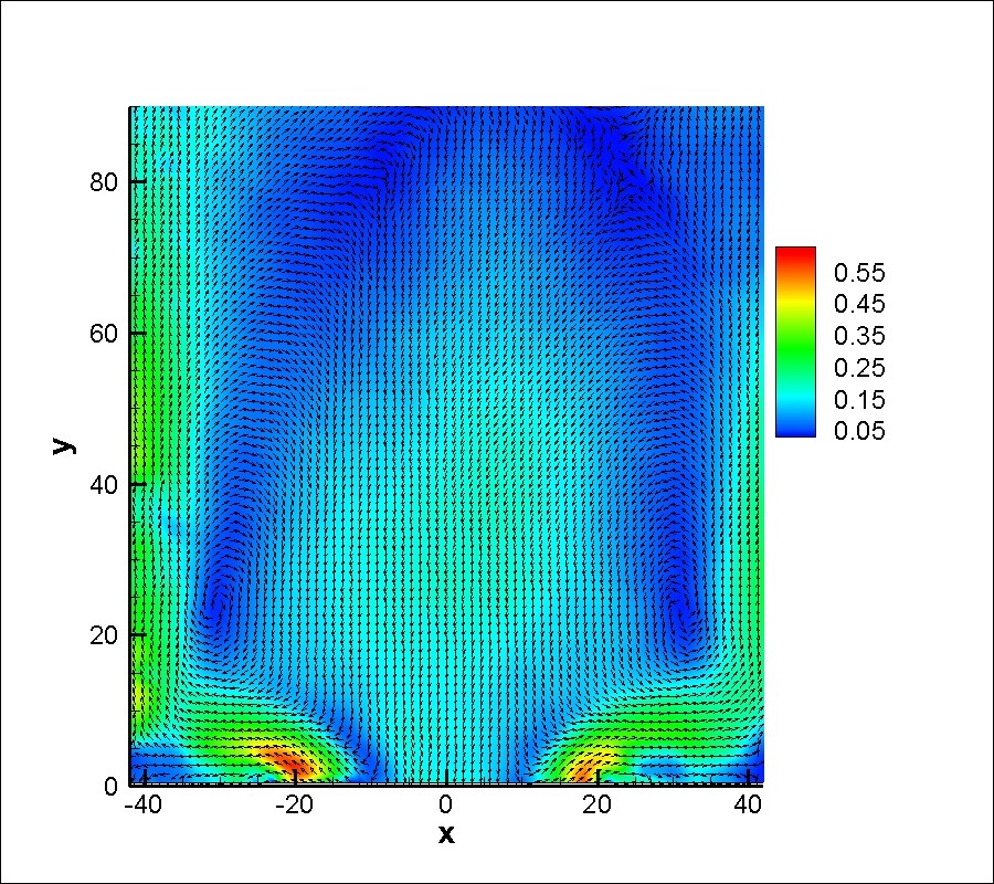
Figure 2 presents the contour of the 2D average velocity magnitude field of the isothermal flow produced by the investigated swirl nozzle. The vectors resulting from the horizontal and vertical cartesian components of the velocity are also provided. At this point it is observed that the produced flow is slightly detached and the ratio between the duct diameter and the recirculation zones is close to a unit. These findings were expected, based on previous studies as well as on the swirl number employed for the designed assembly. These results will allow the further development of the Airblast nozzle design, with the aim of optimizing both the location as well as the size of the vortex break down and the recirculation zones of the flow.
The next steps for the TUB team in Fall 2020 is to install the delivered Airblast assembly to the combustion chamber of the Fluid Dynamics chair at the Institute of Fluid Dynamics and Technical Acoustics and perform measurements under reacting conditions.
References
[1] European Patent Office, Application No./ Patent. No. 06009563.5-, 2006
[2] Leuckel, W.: Swirl Intensities, Swirl Types and Energy Loss of Different Swirl Generating Devices, IFRF-Doc. G 02/a/16, 1967
[3] Fluid Dynamics Chair, Institute of Fluid Dynamics and Technical Acoustics, Technical University of Berlin, Germany (2020). Water test rig. http://fd.tu-berlin.de/en/facilities/water-channel/ Last accessed 12 Jul. 2020